How can I test a PC motherboard with a multimeter?
Are you facing issues with your PC motherboard and wondering how to test it using a multimeter? Don’t worry, we’ve got you covered! In this guide, we’ll walk you through the step-by-step process of testing your PC motherboard with a multimeter, using simple and easy-to-understand language. Say goodbye to technical jargon and get ready to troubleshoot like a pro.
Preparing for Testing
Before you start testing your PC motherboard, it’s crucial to take a few necessary safety precautions. In this section, we will discuss these precautions and guide you on how to create a safe testing environment.
Discuss the necessary safety precautions
Testing a motherboard involves working with delicate electronic components, so it’s essential to prioritize safety. Here are some precautions to keep in mind:
- Power off and unplug: Ensure your computer is completely powered off and unplugged from the electrical outlet before starting the testing process. This will prevent any potential electric shocks or damage to the motherboard.
- Use an anti-static wrist strap: To protect your motherboard from static electricity, wear an anti-static wrist strap. This strap will help discharge any static electricity from your body and prevent it from damaging the sensitive components on the motherboard.
Explain how to properly discharge
Static electricity can wreak havoc on electronic components, especially motherboards. To discharge static electricity properly, follow these steps:
- Ground yourself: Before touching any components, ground yourself by touching a grounded metal object, such as a doorknob or the metal part of a grounded appliance. This will help eliminate any built-up static charge in your body.
- Use an anti-static mat or surface: Place your motherboard on an anti-static mat or a non-conductive surface, such as a wooden table or a cardboard box. This will provide an extra layer of protection against static electricity.
Testing the PC Motherboard
Ready to put your multimeter to use and test your PC motherboard? In this section, we will guide you through the step-by-step process of setting up the multimeter and testing specific components on the motherboard. By following these instructions, you’ll be able to effectively diagnose any issues and ensure accurate results.
Provide step-by-step instructions
Before you begin testing, it’s essential to properly set up your multimeter. Here’s a simple guide to help you:
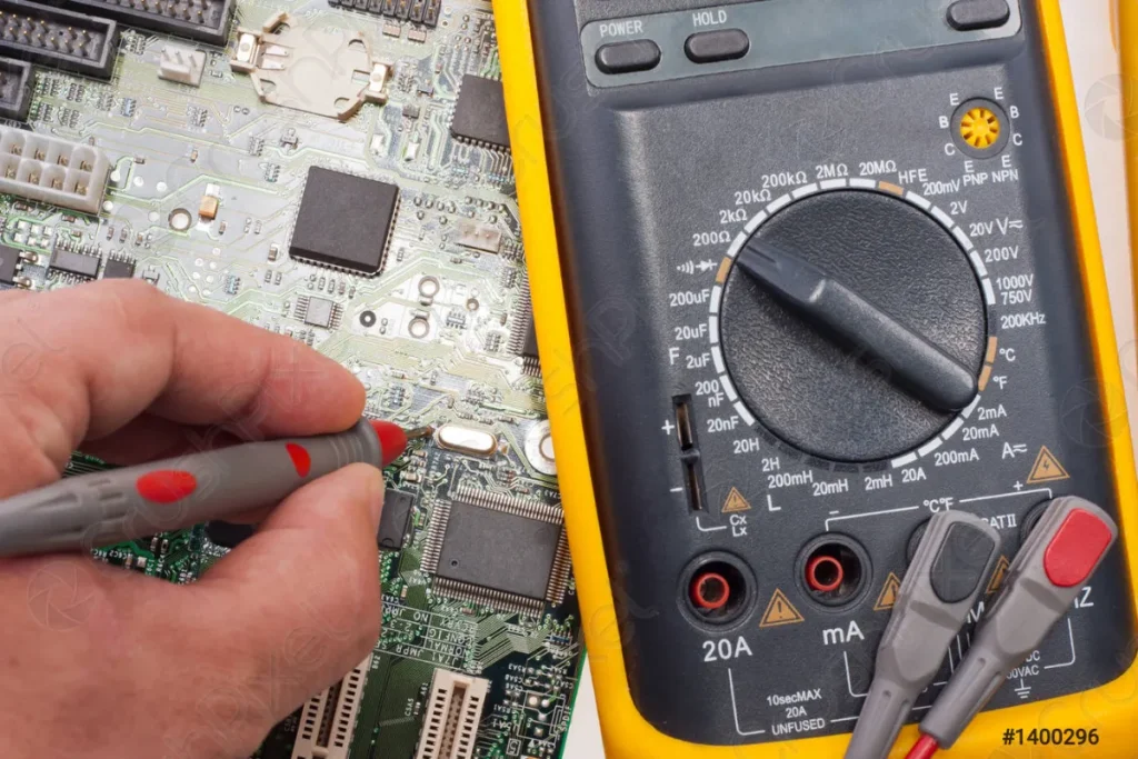
- Select the correct settings: Set your multimeter to the DC voltage mode and ensure it’s set to the appropriate range for the component you’ll be testing. Refer to the multimeter’s user manual for specific instructions.
- Connect the probes: Connect the red probe to the positive (+) terminal and the black probe to the negative (-) terminal on the multimeter. Make sure the probes are securely connected.
Explain how to test specific components
Now that your multimeter is set up, let’s move on to testing specific components on the motherboard:
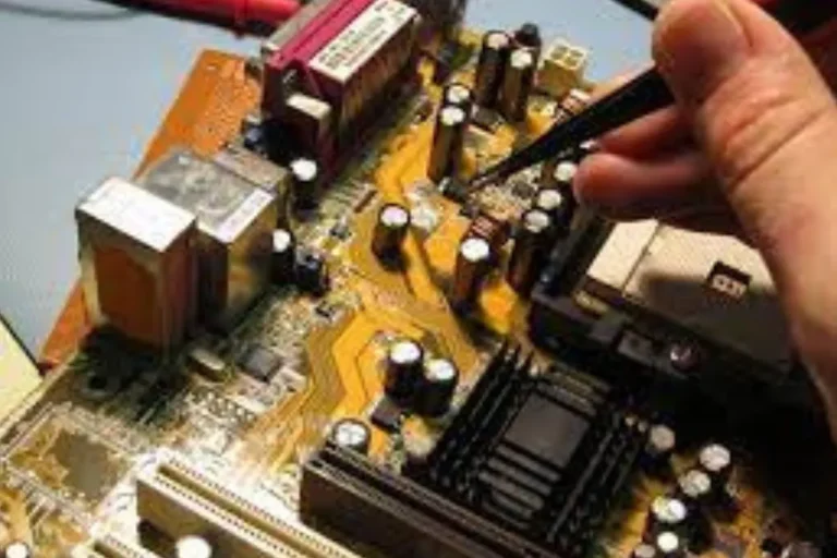
- Testing capacitors: Place the red probe on the capacitor’s positive terminal and the black probe on the negative terminal. The multimeter should display a voltage reading within the acceptable range. If the reading is significantly different or shows no voltage, the capacitor may be faulty.
- Testing voltage regulators: Locate the voltage regulator on the motherboard and identify its input and output pins. Place the red probe on the input pin and the black probe on the ground pin. The multimeter should display the correct voltage output. If the reading is incorrect or shows no voltage, the voltage regulator may be defective.
Interpreting Multimeter Readings
You’ve successfully tested your PC motherboard using a multimeter, but now it’s time to make sense of those readings. In this section, we will guide you through the process of interpreting the readings obtained from the multimeter. Understanding voltage, resistance, and continuity readings will enable you to troubleshoot accurately and resolve any issues.
Explain how to interpret the readings
Reading the multimeter correctly is crucial for accurate diagnostics. Here’s what you need to know:
- Voltage readings: Voltage is measured in volts (V) and indicates the electrical potential difference between two points. A higher voltage reading than expected could indicate a problem with the component or circuit being tested.
- Resistance readings: Resistance is measured in ohms (Ω) and determines the flow of current in a circuit. A higher resistance reading than expected may suggest a faulty component or a broken circuit.
- Continuity readings: Continuity tests whether there is a complete path for electrical current to flow. If the multimeter beeps or displays a low resistance reading, it means there is continuity. If there is no beep or a high resistance reading, it indicates a break in the circuit.
Provide a guide on understanding voltage
The significance of multimeter readings is essential. Here’s a quick guide:
- Voltage readings: Compare the obtained voltage reading with the expected values for the specific component or circuit. Any significant deviations may indicate a problem.
- Resistance readings: Consult the component’s specifications or reference charts to determine the expected resistance value. Deviations from the expected value may signify a faulty component.
- Continuity readings: Use the continuity function to check for breaks in circuits. A beep or low resistance reading indicates continuity, while no beep or high resistance reading suggests a break.
Frequently asked questions
1. How can I determine if my motherboard is faulty?
Start by checking for any physical damages like burnt components or bulging capacitors. Test the motherboard using a multimeter to assess voltage readings and continuity. If you encounter consistent issues or abnormal readings, it may indicate a faulty motherboard.
2. What should I do if my motherboard doesn’t power on?
Firstly, ensure that all power connections are properly seated. Check the power supply unit and cables for any faults. If the issue persists, try removing and reseating components such as RAM and graphics card. If none of these steps work, it’s possible that the motherboard is faulty.
3. How can I troubleshoot random system freezes or crashes?
Start by checking for overheating issues, and ensuring proper cooling for the CPU and GPU. Update your motherboard’s BIOS and device drivers to the latest versions. Scan for malware or viruses. If the problem persists, test each component individually to identify the culprit.
4. What are some common mistakes to avoid during motherboard testing?
Avoid working on the motherboard while it’s powered on or connected to the power supply. Handle components with care, avoiding static discharge by using an anti-static wristband or mat.
5. How can I troubleshoot USB or audio connectivity issues on my motherboard?
Begin by checking if the USB or audio ports are enabled in the BIOS settings. Verify that the correct drivers are installed for these components.
Conclusion
testing a PC motherboard with a multimeter is a valuable skill for troubleshooting hardware issues. By following simple steps and understanding how to interpret multimeter readings, you can confidently diagnose problems and ensure your motherboard is in good working condition.