How do you connect the GPIO to a motherboard?
Are you curious about how to connect GPIO (General Purpose Input/Output) to a motherboard? Look no further! In this guide, we’ll walk you through the process step by step. Whether you’re a beginner or an enthusiast, we’ve got you covered.
Connecting GPIO to a Motherboard
When it comes to connecting GPIO (General Purpose Input/Output) pins to a motherboard, it’s essential to follow a step-by-step guide to ensure a successful connection. In this section, we’ll walk you through the process, discuss proper handling and precautions, and explain the use of jumper wires or cables.
Step-by-Step Guide on Connecting GPIO Pins
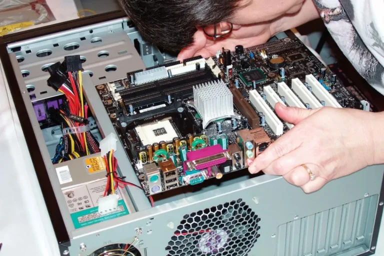
- Identify the GPIO Pins: Start by locating the GPIO pins on your motherboard. These pins are usually labeled and can be found near the edge of the board. Refer to the motherboard’s manual or manufacturer’s website for specific details.
- Prepare the Jumper Wires or Cables: Depending on the type of GPIO connection you’re making, you may need to use jumper wires or cables. Ensure that you have the appropriate wires or cables ready before proceeding.
- Power Off the Motherboard: Before connecting any pins, it’s crucial to power off the motherboard and unplug it from the power source. This precautionary step prevents any accidental damage to the components or electrical mishaps.
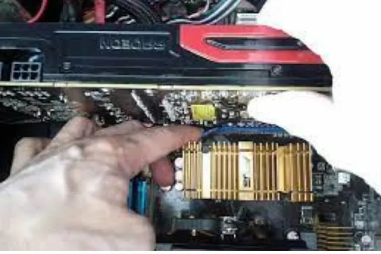
- Connect the GPIO Pins: Carefully align the GPIO pins on the motherboard with the corresponding pins on your device or component. Gently insert the pins, ensuring a secure connection.
- Handle with Care: While connecting the pins, it’s essential to handle them with care. Avoid applying excessive force or bending the pins, as it could damage the motherboard or the connected device.
Proper Handling and Precautions during the Process
- Always handle the motherboard and pins with clean, dry hands to prevent any potential electrostatic damage.
- Avoid touching the sensitive electrical components or circuitry to prevent static discharge.
- Ensure that the motherboard is placed on an anti-static mat or non-conductive surface during the connection process.
- Double-check the alignment of the pins to ensure they are correctly inserted before applying any pressure.
Explaining the Use of Jumper Wires or Cables
Jumper wires or cables play a crucial role in connecting GPIO pins. These wires act as a bridge between the pins on the motherboard and the device or component you want to connect. They provide a secure connection and enable the transfer of signals between the two.
When using jumper wires, make sure to choose the appropriate wire length and connector type for your specific GPIO application. Take care to connect the correct pins on both ends of the wire, following any color-coding or labeling guidelines provided.
Testing and Troubleshooting
When you connect GPIO (General Purpose Input/Output) pins to a motherboard, it’s crucial to verify the connection and address any potential issues that may arise. In this section, we’ll explore how to test the connection, common problems you may encounter, and provide tips for troubleshooting to ensure a successful connection.
Verifying the Connection Using Software or Testing Tools
To ensure that the GPIO connection is functioning correctly, you can utilize software or testing tools. These tools allow you to check if the signals are being transmitted properly and if the connected device or component is responding as expected. Some common software and testing tools include:
- GPIO utility software: This software provides a user-friendly interface to monitor and control GPIO pins. It allows you to read input values, set output values, and test the functionality of the connected devices.
- Multimeter: A multimeter is a versatile tool that can measure voltage levels, continuity, and resistance. By using the multimeter, you can check if the GPIO pins are providing the expected voltage levels or if there are any connectivity issues.
Common Issues and Their Solutions When Connecting GPIO
While connecting GPIO pins, you may encounter some common issues. Here are a few and their possible solutions:
- Loose Connections: If the connection feels loose or unstable, double-check the alignment of the pins and ensure they are securely inserted. You may need to adjust or reinsert the pins for a proper connection.
- Incorrect Pin Configuration: Verify that you have connected the pins correctly, following the pin numbering and configuration guidelines provided by the motherboard manufacturer. Check for any pin mismatches or reversed connections.
- Software Compatibility: Ensure that the software you are using to control the GPIO pins is compatible with your motherboard and the connected devices. Update the software if needed or seek alternative software solutions.
Tips for Troubleshooting and Ensuring a Successful Connection
- Double-check the Connections: Before troubleshooting, review the connections and ensure everything is properly connected and aligned.
- Refer to Documentation: Consult the motherboard’s manual or manufacturer’s website for troubleshooting tips specific to your model. They may provide valuable insights or solutions to common issues.
- Seek Community Support: Engage with online forums or communities dedicated to GPIO connections. Share your problem and seek advice from experienced users who may have encountered similar issues.
Advanced GPIO Connections
If you’re ready to take your GPIO (General Purpose Input/Output) connections to the next level, this section is for you. Here, we’ll dive into the advanced features and capabilities of GPIO, including connecting multiple devices to a single GPIO pin. We’ll also explore some exciting examples of advanced GPIO projects and applications.
Exploring Additional Features and Capabilities of GPIO
GPIO pins offer more than just basic input and output functionality. They can be utilized for various advanced purposes, such as:
- PWM (Pulse Width Modulation): GPIO pins can generate PWM signals, allowing you to control the speed of motors, brightness of LEDs, and other analog-like applications.
- Interrupts: By configuring GPIO pins as interrupts, you can set up event-driven responses. This enables your system to react to specific changes or events in real time.
- Serial Communication: GPIO pins can be utilized for serial communication protocols like I2C or SPI, enabling you to connect and communicate with a wide range of devices.
Connecting Multiple Devices to a Single GPIO Pin
In some cases, you may need to connect multiple devices to a single GPIO pin. This can be achieved through various techniques, including:
- Using Multiplexers: Multiplexers allow you to connect multiple devices to a single GPIO pin by selecting and switching between them using control signals.
- Using Shift Registers: Shift registers allow you to expand the number of output or input pins by using a serial-in, parallel-out, or parallel-in, serial-out shift register. This enables you to control or read data from multiple devices using a single GPIO pin.
Examples of Advanced GPIO Projects and Applications
The possibilities with advanced GPIO connections are limitless. Here are a few exciting examples of projects and applications:
- Home Automation: Use GPIO to control and automate various home devices like lights, thermostats, or security systems.
- Robotics: GPIO can be utilized to control motors, sensors, and actuators in robotics projects, enabling precise control and interaction.
- IoT (Internet of Things): Connect GPIO pins to IoT platforms, allowing you to monitor and control devices remotely, collect data, and create smart home or industrial automation systems.
Frequently asked question
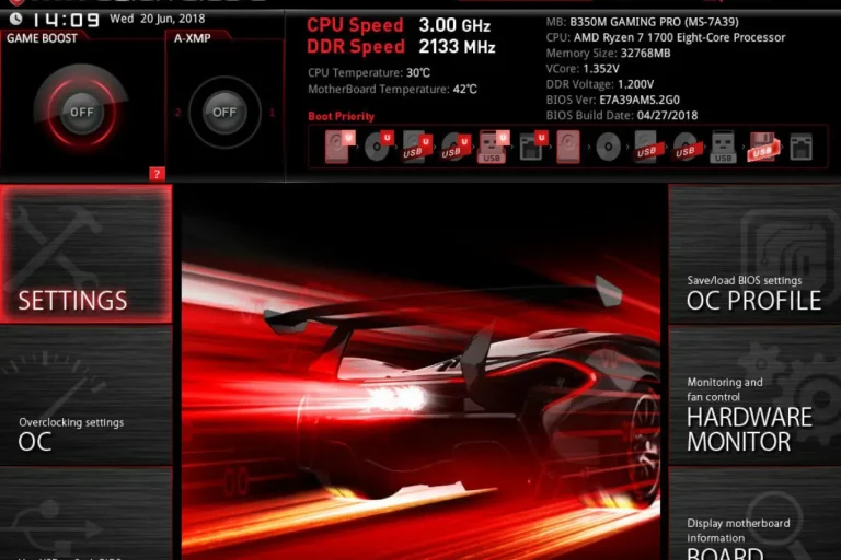
1. How can I identify the GPIO pins on my motherboard?
Consult the motherboard’s manual or manufacturer’s website for a GPIO pin layout diagram. It will provide a clear visual representation of the GPIO pins and their locations.
2. What is pin numbering and how do I understand it?
Pin numbering refers to the labeling system used to identify individual GPIO pins. Most motherboards follow a specific numbering convention, such as the Broadcom numbering scheme or the physical pin numberings.
3. What are the necessary tools and components for a GPIO connection?
The essential tools and components include jumper wires, breadboard, resistors, LEDs, a multimeter, and a computer with GPIO utility software. Additionally, specific components may be required depending on your project requirements, such as sensors, motors, or actuators.
4. Can I use any GPIO pin for my project?
GPIO pins have different functionalities and capabilities. Refer to the motherboard’s documentation to identify which pins are suitable for your specific project requirements. Some pins may have dedicated functions or restrictions, so it’s important to choose the right ones.
5. What precautions should I take when handling GPIO connections?
Always ensure that power is disconnected before making any connections. Double-check the alignment of the pins and make sure they are securely inserted.
Conclusion
In conclusion, connecting GPIO to a motherboard is a straightforward process that requires identifying the GPIO pins, understanding the pin numbering, and gathering the necessary tools and components. By referring to the motherboard’s documentation and following the provided guidelines, you can confidently embark on your GPIO connection journey.